|
|
| Logic
Gates |
|
|
A digital circuit which one or more input signals but only one
output signal is called Logical gates. |
|
|
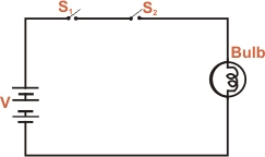
Since a logic gate is a switching
circuit (i.e. a digital circuit), its outputs can have only
one of the two possible states viz. either a high voltage
(1) or a low voltage(0) - it is either ON or OFF. Whether the
output voltage of logic gate is high (1) or low (0) will depend
upon the condition at its input. Fig. shows the basic idea
of a logic gate using switches.
|
|
|
|
|
|
(I) When S1 and S2 are open, the bulb
is OFF.
(II) When S1 is open and S2 closed,
the
bulb is OFF.
(III) When S2 is open and S1 closed,
the
bulb is OFF.
(IV) When both S1 and S2 are closed,
the
bulb is ON.
Note: The output (OFF or ON) depends upon the conditions at the input. |
|
|
S1 |
S2 |
Bulb |
|
open |
open |
OFF |
open |
closed |
OFF |
closed |
open |
OFF |
closed |
closed |
ON |
|
|
| S1 |
S2 |
Bulb |
|
0 |
0 |
0 |
0 |
1 |
0 |
1 |
0 |
0 |
1 |
1 |
1 |
|
|
|
|
The four possible combination of switches S1 and S2
are shown in the table below. It is clear that when either of
the switches (S1 or S2)or both are open,
the bulb is OFF. In binary language , when either of the inputs
or both the inputs are low (0), the output is low. When both
switches are closed, the bulb is ON, It is a usual practice
to show the conditions at the input and output of a logic gate
in the binary form as shown in the table above. Such a table
is calls truth table. |
|
|
The term "logic" is usually used to refer to a decision-marking
process. A logic gate makes logic decision regarding the existence
of output depending upon the nature of the input. Hence such
circuits are called logic circuit. |